This page contains the online version of the manual that comes with the TC9106-1 or the TC9119-1 add-on board
It is illegal in many countries to transmit outside of the normal CB band, this board is to be used for RX only, do not transmit out side of the legal band, you are responsible for the manner in which you use the conversion board.
This board will increase the possible frequency range by 3 bands, as follows:
If the board is installed on a 40 channel radio you will get low, mid (FCC), high, and the old UK 27/81 band! (assuming that the radio is broad band enough to be able to produce the full range), that is an extra 3 bands !
Of course you do not need to enable every option on the board, you can choose which ones you wish to use, if you only want the UK and mid band that is fine, or if you only want to have the low band and mid band, it is up to you.
I have built as much data into the EPROM as I could fit on it so that there are lots of options that can be used. This board is not suitable for some radios, please read further in this manual to see if your radio can use this version of the board, (I can make custom boards at an additional cost).
A degree of electronic skill is required to install this expansion board, also the radio may need to be tuned or broad banded to allow for the extra frequency coverage that this board will allow.
I have made a quite simple installation look complex, please do not be concerned about the complexity of this manual,look at the programming chart I have included, this will show what options and programming requirements there are for the radio.
I have tried to include as much information as possible in this manual to try and cover all possible requirements and radios, I am sure that there will be times when some people will need more information or assistance and when this occurs I can be contacted either through my web site at https://www.radiomods.co.nz/
This board was designed to convert radios with these PLL numbers:
When I installed this board in my UK27/81 radio, an Audioline 340 (PA 034AA) I got the following coverage:
26.515 - 26.955 Low band
26.965 - 27.405 Mid, FCC band (New bands)
27.415 - 27.855 High band
27.601 - 27.991 UK band (Existing band)
If this board is installed in a radio that has the TC9106 PLL you will get the same coverage as above.
Here is a list of radios that I designed this board for, I got the binary code information from the great books written by Lou Franklin (http://www.cbcintl.com), the list is probably much bigger than this as the only critical factors are that the radio uses the correct binary codes and that the board will physically fit inside the radio.
TC9106 PLL
Cobra 18LTD, 20LTD, 21LTD, 21LTD Classic, 21GTL, 25GTL, 25LTD, Craig L104, GE 3-5804B,5804F, 5805, 5815A, K40-8, Midland 200M, 77-824B,NDI PC101, PC102, Pearce Simpson Super Tomcat MKII, President P220, Andrew J, AR7, AR44, AX44, AR711, AX711,Herbert, Taylor, P200, P210, Realistic TRC425, TRC426, TRC427, TRC473, TRC474, Teaberry Stalker III, Uniden AX-43, PC-3, PC33, PC33X, PC55, PC55X, PC66, PC66XL, PC-404, PRO-540e.
TC9119 PLL
Audioline 340, 341, 345, Tandy TRC2000, TRC2001, TRC2002, Uniace 100, 200, 300.
Please note that I am not able to test this unit in every make and model, but as long as the radio uses one of the PLL's listed you will have no problems.
OK, now on to the nuts and bolts (or is the resistors and capacitors ?)....
Be careful when handling the EPROM, it is a static sensitive device and may be damaged if care is not taken to avoid static build up, whenever you pick up or put down the device ALWAYS touch the surface first so that static does not pass through the device, the best thing is to use a antistatic wrist strap at all times.
After doing this you should have the board connected to +12V, earth, 8 inputs from the PLL pin holes to the EPROM (D0-D7), 4 outputs from the board to the PLL pin locations 1,2,7 and 9, the EPROM control lines connected to your switches:
11. Turn the radio on and test everything thoroughly, all bands, both existing and new, Low band, Mid band, High band and UK band.
12. Tune or broad band anything that needs adjusting (see tips later in manual).
13. If all is OK and you did not make any mistakes, CAREFULLY Stick down the EPROM board with the double sided foam tape supplied, do not apply too much pressure.
14. Close up the radio and enjoy your new frequencies !
Broad banding
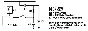
Most radios will need it to be done, but you may not need to, an easy way is to tune the radio for the upper frequencies (but as low as you can without problems) and then add the circuit below to the low bands to extend the tuning range of a problem tuning can.
Also some tuning cans may only be using part of the internal coils, if only one of the outer pins is connected and the middle pin is used, cut the track that goes to the middle pin and connect the track to the unused outer pin, this increases the bandwidth of the can making it cover more channels.
Here is some ASCII art:
                  _______
   Unused pin--> | o O O |
                 |       |     <----Screening can viewed from trackside

                 | O   O |
                  -------
This table shows you all of the possible programming arrangements with this EPROM board and what input codes enable which bands, the inputs only need to be pulled down to 0 Volts, they do not need to be pulled high by the switch, so for the UK band both of the band wires could be left disconnected, for the Mid band you only need to pull B2 low.
|
Band
|
B1
|
B2
|
|
Low
|
0
|
0
|
|
Mid
|
1
|
0
|
|
High
|
0
|
1
|
|
UK
|
1
|
1
|
1. I checked the PLL was a TC9106 (or TC9119 for UK).
2. I decided that I only wanted to have the UK and the Mid bands.
3. I checked the programming chart and found that for the UK and Mid bands I only need to control B2.
5. I made available the switch required for the new function and wired it to the Eprom board as shown below:
             UK/Mid    <---Switch function
              ___       ___
             | O | <--- UK (switch up)
   B2  <=====|=O |
   0V <======|=O | <--- Mid (switch down)
              SW1
6. I removed the PLL making a note of which way around it was, pin 1 of the PLL is always the pin on the corner at the bottom left when viewed with the markings the correct way up, there may also be either a notch or a dot at that side.
7. I connected the EPROM inputs (A0-A7) to the PLL pin locations as follows:
|
PLL pin number
|
10
|
11
|
12
|
13
|
14
|
15
|
16
|
17
|
|
EPROM input number
|
A0
|
A1
|
A2
|
A3
|
A4
|
A5
|
A6
|
A7
|
8. I connected the outputs of the board to the PLL pin locations shown below:
|
PLL pin number
|
7
|
1
|
9
|
2
|
|
EPROM output number
|
P1
|
P2
|
P3
|
P4
|
9. Then I connected the power wires (+12V and 0V) from the board to the radio.
10. I solder the jumpers between the PLL pin locations 5,6 and earth, and between 1 and 4.
11. I lifted one end of the capacitor that is in series with the 10.240 crystal and added a 39pF cap in series with the original, then added the switch wire across the new cap so that when in the UK band the new cap is bypassed, causing a 4 kHz increase in frequency when on the low, mid of high bands.
12. I double checked all of my wiring and that I had got the input and output connection the correct way around etc.
13. I slipped the EPROM board into a bag to protect it.
14. I turned on the radio and checked for both normal operation and the new expanded functions I set up (UK and Mid bands).
15. I checked to make sure that the EPROM board was not receiving a 12V supply after I turned the radio off.
16. All was working correctly so I stuck the board down in the radio using the double sided tape to finish the installation.
17. I did not need to broad band the radio, so I have finished the installation.
18. I closed the radio back up.
EPROM board is not working at all
Check jumpers on pins 1 goes to 4 and jumper on pins 5,6 go to 0 Volts track
Check that you have not miss-programmed the jumpers or switches, 1 incorrect jumper or selection setting could stop the EPROM from recognizing the binary codes.
You have not attached the outputs form the board to the correct PLL pin locations.
Only some bands are working
There could be a mistake with the programming switches not giving the EPROM a 0V signal, or a jumper has not been or added correctly.
You did broad band the radio and the miss-alignment causes the radio to not work on some bands.
Some channels do not work on a certain band
If there is a large gap of channels missing it may be a jumper or switch programming problem.
The radio may need to be re-tuned slightly or broad banded.
The EPROM may have been damaged by static electricity during handling.
The EPROM may have been damaged by incorrect wiring.
Note: All EPROM's are checked after I have programed them to ensure that they have accepted the programming information correctly and that the EPROM is not faulty.
E-mail me if you have any questions or concerns about installation.
All boards are installed at your own risk,
(it is not my fault if you make a mistake and damage your equipment).
I build and test these circuits myself before shipping them, so I know that the boards are working correctly when you receive them.
This counter shows the number of hits since the 26th May 2001
Copyright © RadioMods 1997-2024