
This page contains the online version of the manual that comes with the uPD858-1 add-on board
It is illegal in many countries to transmit outside of the normal CB band, this board is to be used for RX only, do not transmit out side of the legal band, you are responsible for the manor in which you use the conversion board.
If the board is installed on a 40 channel radio you will get low-low, low, mid (FCC), high, NZ, UK and a 10kHz shift on all bands ! (if the radio is broad band enough), that will give you an extra 5 bands !
NOTE: Some radios will not be able to get right down to 26.065 on the Down 2 band, this is due to the VCO running out of range, you may get down to around 26.085 or so before the VCO quits, it will depend on the radio.
You do not need to enable every option on the board, you can choose which ones you wish to use, if you only want the UK band that is fine, or if you only want to have the down band and up bands with +10 kHz shift that is fine too, it is up to you, I have built a great deal of data into the EPROM so that there are lots of options that may be used.
If this board does not provide a specific coverage of frequencies that you would like I can make custom boards at an additional cost provided that you can supply detailed info on your radio and your requirements.
A degree of electronic skill is required to install this expansion board, also the radio may need to be tuned or broad banded to allow for the extra frequency coverage that this board will allow.
I have made a quite simple installation look complex, please do not be concerned about the complexity of this manual, once you know the BCD code range used in your radio you just cross check it against the programming chart I have included, this will show what options and programming requirements there are for it.
I have tried to include as much information as possible in this manual to try and cover all possible requirements and radios, I am sure that there will be times when some people will need more information or assistance and when this occurs I can be contacted either through my web site at https://www.radiomods.co.nz/ or by e-mailing me.
This board will convert any radio using the uPD858 as long as the BCD codes are correct (see below).
For the board to function correctly the PLL must be using the BCD code range of 91-135 (CH1-CH40), this is the code for SSB units.
To work out the BCD code just measure the voltage on pins 13 through to 22 of the PLL with the radio on channel 1 mid (FCC) band.
For a code of 91 pins 13,17 and 20 will be high. Pins 14,15,16,18,19,21 and 22 will be at 0 V.
The extra coverage that should be gained is as follows:
For all radios, Down 2 bands, Down 1 band, Up 1 Band, New Zealand 40 Channels (down 63 channels), UK 27/81 Channels (up 64 channels without �A� channel hops) and +10KHz shift on all bands, the NZ and UK bands are operated from the mid (FCC) band (the normal band for 40 channel radios).
When I installed this board in a Ferris SSB5000 (a 40 channel AM/SSB radio using the PC346A PCB) I got the following coverage:
26.330 - 26.770 - NZ band, clarified
26.065 - 26.505 - Low Low
26.515 - 26.955 - Low
26.965 - 27.405 - Mid, the normal band
27.415 - 27.855 - High
27.601 - 27.991 - UK band, clarified
And a +10 kHz shift on all bands.
That gives this radio a total of 194 channels (including the 10kHz shift).
A point of interest is when on the "UK"band as it gives 40 consecutive channels without the �A� channel hops, but of course the +10kHz shift can sort those out for you !
Here is a list of radios that I designed this board for, I got the BCD code information from the great books written by Lou Franklin (http://www.cbcintl.com), the list is probably much bigger than this as the only critical factors are that the radio uses the correct binary codes and that the board will physically fit inside the radio.
SSB models:
Cobra 138XLR, Cobra 139XLR, Courier Centurion PLL, Centurion 40D, Gladiator PLL, Sparton PLL, Fanon Fanfare 350F, Ferris SSB5000, Midland 79-893, Palomar SSB500 (early), President Adams, Grant (early), Madison (early), Washington (early), Realistic TRC449, TRC457, TRC458, Robyn SB510D, SB520D, Stag 357, Teabury Stalker 101, 102, 202, WKS 1001.
Please note that I am not able to test this unit in every make and model, but as long as the BCD codes match the ones I listed you will have no problems with the boards compatibility.
OK, now on to the nuts and bolts (or is the resistors and capacitors ?)....
Be careful when handling the EPROM, it is a static sensitive device and may be damaged if care is not taken to avoid static build up, whenever you pick up or put down the device ALWAYS touch the surface first so that static does not pass through the device, the best thing is to use a antistatic wrist strap at all times.
1. Check for the correct BCD code at the PLL pins, see note earlier in manual.
2. Decide what bands you require the board to produce (see note below).
3. Decide how you are going to control the new bands, existing panel switches, new toggle switches etc.
4. Cut the tracks that go to pins 13 through to 21 of the PLL to isolate them from the channel selector and jumper connections.
5. Solder a 4.7 K Ohm resistor across the cut track for pin 21.
6. Solder the ribbon cable to the PLL pins (D0-D7, see picture later) and to the channel selector side of the cut tracks (A0-A6, see picture later).
7. Solder the EPROM board to a good earth point on the main board (0V).
8. Solder the +12V wire to the main radio supply, make sure that it is from after the on/off switch so that the board is not powered when the radio is turned off.
9. Connect the board to the switches to select the required bands and functions.
10. Go back to step 1 and double check everything on each step.
11. Triple check everything, I mean it !
After doing this you should have the board connected to +12V, earth, 8 outputs from the EPROM to the PLL (D0-D7), 7 inputs from the cut tracks on the channel selector side to the inputs of the EPROM (A0-A6), the EPROM control lines connected to your switches: A7 + A8 = DOWN 2 band, A7 = DOWN band, A8 = UP band, A9 + A7(A8) = NZ(UK), A10 = +10kHz step.
See the programming chart later in this manual for a completely comprehensive listing of control functions and binary codes required.
12. Turn the radio on and test everything thoroughly, all bands, both existing and new, Down bands, Up band, NZ/UK and 10K shift on each.
13. Tune or broad band anything that needs adjusting (see tips later in manual).
14. If all is OK and you did not make any mistakes, CAREFULLY heat shrink the Eprom board with the tube supplied, do not apply too much heat.
15. Close up the radio and enjoy your new frequencies !
This picture shows the EPROM board wiring diagram with its inputs (A0-A6) its programming/switch inputs (A7-A10, (or A l l if fitted with a 2732 EPROM) and the 5V, 0V rails), its outputs (D0-D7) and its power supply connections (+12V and 0V).
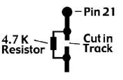
The picture below shows the arrangement used for pin 21 on the PLL, where the track has to be cut and bridged with a 4.7 K Ohm resistor
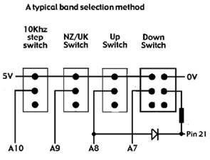
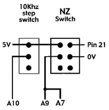
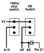
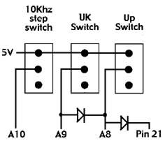
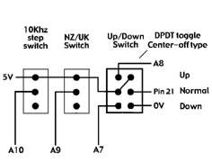
These pictures show various methods of band selection, any one of the switches can be omitted, the NZ/UK switch can be used without an Up / Down band switch, also you can have it set up so that it automatically turns on the Up (for UK) / Down (for NZ) band when you activate it (required for it to work), as longs as diode steering is used to select either the A7 (for NZ) or A8 (for UK) lines when activated.
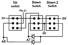
For the Down 2 band you must use diode steering to send the control signals to the A7 and A8 lines at the same time (see picture below).
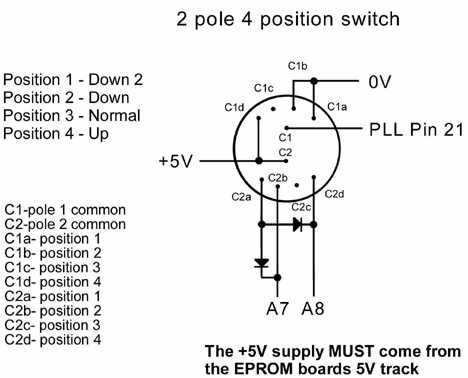
Note the 4.7K resistor directly after one of the switches to prevent a short circuit if Up and Down bands are selected at the same time, and the switching of pin 21, also note the use of a center-off type toggle switch, this can simplify installation greatly, compare it with the other version that gives the same bands.
The picture below shows the PCB layout, I have used pull down resistors on the board to simplify the boards installation.
To control one of the programming lines just connect a wire to the required line, A10 for example, it is the control line for the 10 kHz shift, just pull it high (5V) and it will activate it.
You must only use the 5V supply that comes from the EPROM board itself for all programming switches, this is very important as you must not use too high a voltage otherwise you will damage the EPROM.
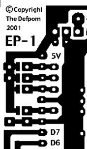
The 5V rail is the one going down the left side, the 0V is the one that is horizontal above D7 and connects to the main earth track, you can also see the pads that allow the pins to be tied high if needed without having to attach jumper wires (only if a pin needs to be programmed to be high all of the time), you will notice that for boards using a 2716 EPROM the A11 pin is already pulled high.
PLL Pin 21 switching
When in normal bands (all extras turned off) pin 21 must be connected as normal as it changes from low to high in the normal range of codes, this is done by the 4.7 K Ohm resistor that is soldered across the cut track, when the DOWN 2, DOWN or NZ band is activated the pin must be low all of the time, so it must be pulled low by the switches, but when in the UP or UK bands it must be pulled high instead, this is done by manually switching the pin with the UP or UK switch.
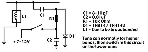
Broad banding
Most radios will not need it to be done, but you may need to, an easy way is to tune the radio for the upper frequencies (but as low as you can without problems) and then add the circuit below to the low bands to extend the tuning range of a problem tuning can.
The clarifier on most of the SSB radios gives about kHz of slide, which is enough for most purposes, but if you want to add a little more then add a 4.7 uH coil to the varactor diodes, they are D45 (AM), D41 (USB) and D43 (LSB).
This section show you all of the possible programming arrangements with this EPROM and what input codes allow which outputs from the EPROM board, just look up the input code range(s) that your radio uses and look at the possible operating bands and programming information for the board.
|
Input code
|
A7
|
A8
|
A9
|
A10
|
Output Code
|
Band
|
|
91-135
|
0
|
0
|
0
|
0
|
91-135
|
Normal
|
|
1
|
1
|
0
|
0
|
01-45
|
Down 2
|
|
|
1
|
0
|
0
|
0
|
46-90
|
Down
|
|
|
1
|
0
|
1
|
0
|
28-72
|
NZ
|
|
|
0
|
1
|
0
|
0
|
136-180
|
Up
|
|
|
0
|
1
|
1
|
0
|
155-194
|
UK
|
|
|
0
|
0
|
0
|
1
|
92-136
|
Normal +10kHz
|
|
|
1
|
1
|
0
|
1
|
02-46
|
Down 2 +10kHz
|
|
|
1
|
0
|
0
|
1
|
47-91
|
Down +10kHz
|
|
|
0
|
1
|
0
|
1
|
137-181
|
Up +10kHz
|
|
|
1
|
0
|
1
|
1
|
29-73
|
NZ +10kHz
|
|
|
0
|
1
|
1
|
1
|
156-195
|
UK +10kHz
|
NOTE: A "1" means high, a "0" means low
NOTE: the output codes may say a figure greater than 99, the 10kHz can only supply a code as high as 99, that is why we must pull the PLL pin 21 high/low as needed to give the final code of over 99, for example, a code of 136 requires all 8 bits from the EPROM and 1 more bit (the 100 bit) to be high as well, so we pull pin 21 high as it is the pin for a code of 100, I hope this helps to explain it for those people who know that EPROM's only have a possible output code of 99 when used in BCD.
Here are the general functions of the EPROM's A7,A8,A9 and A10 inputs:
A7 = Down band selector. (used with A8 for Down 2 band)
A8 = Up band selector. (used with A7 for Down 2 band)
A9 = NZ/UK band selector (used in conjunction with A7 (NZ) and A8 (UK).
A10 = +10 kHz shift.
If you do not know how to calculate the binary number (also known as N code) read this.
|
PLL pin number
|
13
|
14
|
15
|
16
|
17
|
18
|
19
|
20
|
21
|
22
|
|
Binary weight
|
1
|
2
|
4
|
8
|
10
|
20
|
40
|
80
|
100
|
200
|
So if pins 13,17 and 20 where high and the rest where low (at 0V) you would have a BCD code of 91 (1+10+80=91), you just ignore the pins that are low.
1. I checked the PLL pins and found that it used a code range of 91-135.
2. I decided that I only wanted to have a 10 kHz shift and the Down band.
3. I checked the programming chart and found that for a code range of 91-135 the 10 kHz step uses A10 and the Down band uses A7.
4. I found the connections on the EPROM board for A7 and A10.
5. I cut the tracks on the radio PCB for PLL pins 13-21.
6. I made available the switches required for the new functions and wired them to the EPROM board as shown below :
            +10kHz   Down band    <---Switch function
              ___       _____
   5V <======|=O=|=====|=O O=|====> 0V <--Function ON (switch up)
   A10 <=====|=O | A7==|=O O=|====> PLL pin 21
             | O |     | O O |         <--Function OFF (switch down)
              SW1        SW2
7. I connected the EPROM inputs (A0-A6) to the channel selector side of the cut tracks as shown below, note that A6 is not connected to pin 19 but pin 20 instead, this is important !:
 PLL pin           13 14 15 16 17 18 19 20 21
                    |  |  |  |  |  |  |  |  |
Cut in tracks -->  ---------------------------
                    |  |  |  |  |  |  |  |  I
EPROM input        A0 A1 A2 A3 A4 A5  - A6 4.7K RESISTOR
                    |  |  |  |  |  |  |  |  |
Channel selector    |  |  |  |  |  |  |  |  |
connections ---->   O  O  O  O  O  O  O  O  O
8. I connected the EPROM outputs (D0-D7) to the PLL pins as follows:
|
PLL pin number
|
13
|
14
|
15
|
16
|
17
|
18
|
19
|
20
|
|
EPROM output number
|
D0
|
D1
|
D2
|
D3
|
D4
|
D5
|
D6
|
D7
|
8a. I also connected a 4.7 K Ohm resistor across the cut in the track for pin 21, this will allow normal control when in the normal band and allow me to pull it low whenever the Down band switch is activated.
9. Then I connected the power wires (+12V and 0V) to the radio.
10. I double checked all of my wiring, checked that I had cut the tracks correctly on the EPROM and radio boards and that I had got the input and output connection the correct way around etc.
11. I slipped the EPROM board into its heat shrink tube to protect it.
12. I turned on the radio and checked for both normal operation and the new expanded functions I set up (+10kHz step and the Down band).
13. I checked to make sure that the EPROM board was not receiving a 12V supply after I turned the radio off.
14. All was working correctly so I applied heat to the heat shrink tube to finish the installation.
15. I did not need to broad band the radio, so I have finished the installation.
16. I closed the radio back up.
EPROM is not working at all
Check jumper on pin 21, for a EPROM marked as a 2716 the track to it should be cut and the pin should be jumpered to the +5V rail on the board, I shall do this when I make the board but you may disturb it.
Check that you have not miss-programmed the jumpers or switches, 1 incorrect jumper or selection setting could stop the EPROM recognizing the binary codes.
The radio does not use the correct binary codes required for the EPROM to work in it, see note about binary codes that are supported earlier in this manual.
Only some bands are working
There could be a mistake with the programming switches not giving the EPROM a 5v signal, or a track has not been cut correctly.
You did not notice that the radio uses more than one set of binary codes and you have not set the switches for the other codes.
You did not add the 4.7 K Ohm resistor across the cut in the track for pin 21 or correctly attach the diodes on the switches for the diode steering.
Some channels do not work on a certain band
If there is a large gap of channels missing it may be a short or switch programming problem.
Run a knife carefully between the tracks on the EPROM board just encase there is a slight bridge between them, check between the pads where the wires are soldered on.
The EPROM may have been damaged by static electricity during handling.
The EPROM may have been damaged by incorrect wiring.
You may not have attached the A6 wire to pin 20, you may have put it on pin 19 by mistake.
Note: All EPROM's are checked after I have programed them to ensure that they have accepted the programming information correctly and that the EPROM is not faulty.
E-mail me if you have any questions or concerns about installation.
All boards are installed at your own risk,
(it is not my fault if you make a mistake and damage your equipment).
I build and test these circuits myself before shipping them, so I know that the boards are working correctly when you receive them.
This counter shows the number of hits since the 8th May 2001
Copyright © RadioMods 1997-2024