 ž
ž

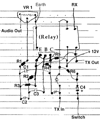
Thank you to Roger R. for making this diagram for me to add to the site.
a single tone end of transmission bleep
 ž
ž

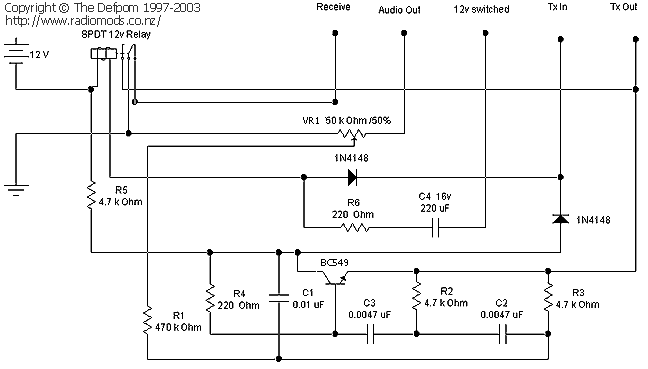
Thank you to Roger R. for making this diagram for me to add to the site.
Component List
VR 1 - 50K
TR 1 - BC549
OR SUBSTITUTE EITHER OF THESE:
2N5818, 2N4401
R1=470K----R2=4.7K----R3=4.7K----R4=220K----R5=4.7K----R6=220 Ohm
C1=0.01Uf Ceramic (103) ---C2=0.0047 Uf Ceramic (472) ---C3=0.0047 Uf Ceramic (472)
C4=220 Uf 16 Volt Elect. cap (this capacitor controls the duration of the bleep and may need to be a different value because the type of relay used may need more current.)
The two diodes are of the 4148/914 silicon type
The relay is a SPDT 12 Volt miniature type
When the switch wire is connected to +12 VDC the bleep is enabled (will sound when you de-key), when the wire is not connected the bleep is disabled (will not sound when you de-key).
TX OUT--------TX wire that was removed from the mike socket.
RX OUT--------RX wire that was removed from the mike socket.
AUDIO OUT---Attach to audio wire on the mike socket.
TX IN-----------Attach to the TX pin on the mike socket.
SWITCH--------Wire as shown in the above picture.
+ 12 VDC-------Attach to the constant + 12 V supply on the radio's on/off
switch
(make sure you take it after the switch, otherwise the bleep will be powered
up even when the set is OFF !)
EARTH---------Attach to the Earth/Ground/-0 Vdc.

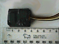
This is a finished bleep that is ready to be installed !
If you build this unit and like it please email me !
Have Fun !
This counter shows the number of hits since the 24th August 1998
Copyright © RadioMods 1997-2024